14th August 2007

OK, this month's excuse for the lack of progress is having been on the se7ens list tour of Norway in the Striker. I think it's fair to say that a tonkingly good time was had by all, and that we proved beyond any reasonable doubt that hairpin-laden mountain roads are quite fun to drive up and down...

Actually, the other excuse is that a 10 day tour really inspired me to finish off the Furybird II, which is to be my touring car, as I think it'll be a bit more civilised than the Striker, which although as mad as a barrel of monkeys and great fun, is a bit brutal for long tours. But despite all this, I did get
some work done on the 'Racer, details of which are set out in mind-numbing detail below.

Dampers - an update

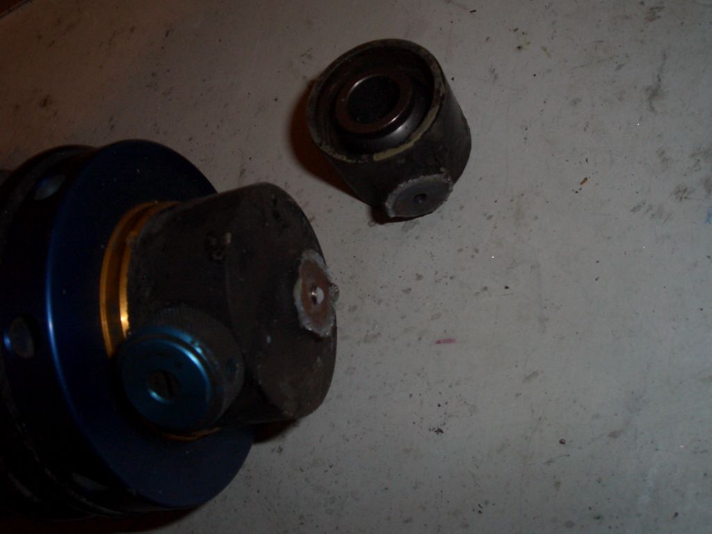
But before I go into detail on the work done, an update on the damper situation, which at the end of last month's episode wasn't looking too good. I sent an e-mail to Guy Evans, head honcho at Nitron, asking if they'd be able to fix the bust damper. He wrote back saying that they didn't support these dampers any more, and there was nothing they could do. He suggested I weld it back together again, saying that the damper would have a 50% chance of working if I did...

Now, I don't think I'm a particularly stroppy person but the dampers are only 5 years old, cost about 800 quid when I bought them, and were sold as being factory servicable. I don't think that 5 years is outside the normal working lifespan of a set of dampers, and as such I was a bit miffed that Nitron's aftersales support seemed to amount to shrugged shoulders. So I sent a rather terse e-mail back to Guy Evans suggesting, in entirely non-insulting language, that I didn't think this was particularly stellar customer service and suggesting that I might be buying a couple of sets of ProTech shocks in the near future rather than the Nitron NTRs I'd been planning to get for the FurybirdII.

Guy Evans, in his reply, said that he found my e-mail 'annoying' and 'offensive', which I found surprising since it was merely commenting (justifiably I'd say) on his firm's customer service. He said that the NTXs (the dampers I had) were a product they'd stopped supporting 2 years ago (only a year after they stopped selling them) and that they were a product they were 'glad to have left behind'. Apparently they decided stop servicing them because the tools required to service them were 'taking up space in the workshop'. Yup, you couldn't make it up.

So after explaining how crap the product he used to sell was, clarifying that customer service depends on whether they've got enough spare workshop space and complaining about my insolence in criticising his firm, Mr. Evans said he 'always' offered a discount on a new set of dampers in a situation like this (news to me, he hadn't mentioned it in his earlier e-mail).

I replied in a carefully worded e-mail so as to not bruise Mr. Evans' tender feelings or upset him again, asking what sort of discount was on the table, and he replied saying 30%. Now I was going to get a pair of NTRs for the Furybird anyway, so I wrote back saying that was fine and asking for a total figure including P&P, VAT and the cost of the little mounting top-hat pieces. And never heard anything more.

So, congratulations to Nitron for continuing the great tradition of British industry. Great product, reasonable prices, and a quite
appalling level of customer service. We'll put Nitron's dampers in the same pile as Hi-Spec Motorsport's brakes and Barmby Engineering's wheels.

The one ray of sunshine was that Guy Evans let slip that the ProTechs were designed by him, and are internally the same as the NTX dampers I already had. Now I've always been very happy with the performance of the NTXs, and Guy even admitted that they'd probably be fine on a car as light as a BEC racer. So, 2 sets of ProTechs it is. And I have to say that so far ProTech have been absolutely fantastic on the old customer service front - let's see if that continues...

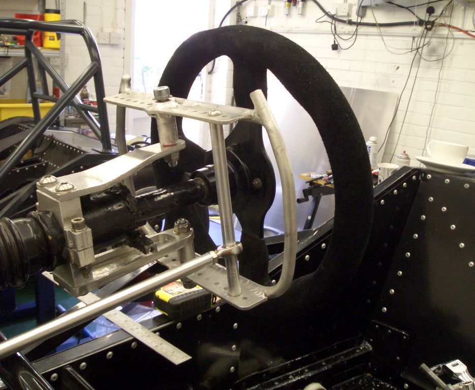
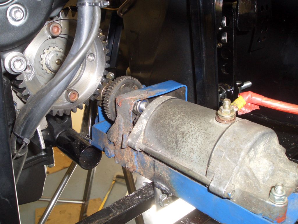
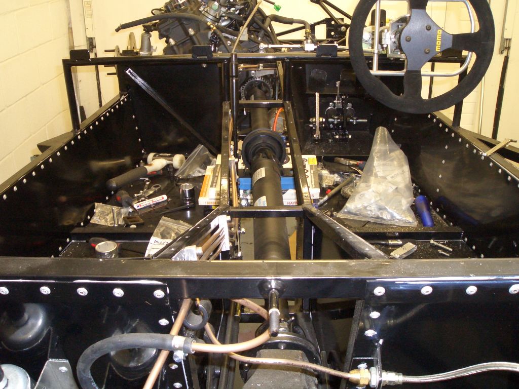
Anyway, rant over - onto the engineering...

Gear linkage

  Having mounted the paddles, it was time to connect them to the shift lever on the engine/gearbox. I had intended to mount the long rod linkage from the paddles to the bellcrank directly onto the paddle with the rosejoint being bolted onto the flat plate at the bottom of the paddle (the one with all the holes in it for precisely that reason).

Trouble was, the scuttle tube on the chassis (the one that runs along the lower edge of the dashboard and helps it shake around wildly over bumps) was in the way. And if I used the top plate as the mounting point for the rod linkage, I'd need a bellcrank about a foot tall.

So I made up this bar to mount the rosejoint onto. I thought about just using a long length of studding with some ali tubular spaces, but this seemed a bit heavy. So this is actually two length of ali, one slotting inside the other once the rosejoint's been fitted into it. The stainless button head bolts at either end are only 16mm long, but it's plenty stiff - the two ali sections are almost an interference fit. Thank the FSM for lathes...

The paddles go forwards and backwards, obviously, while the shifter on the engine goes side to side. So a bellcrank's needed to switch direction of the force exerted on the paddles. And here it is. Machined from billet ali, naturally, it looks a bit chunky but is actually pretty light - there's a lot of material that's been machined away. Thank the FSM for milling machines...

The rosejoints are little M6 ones I got off eBay. A bargain at less than a fiver each, I doubt they're that studly, but I've kept reminding myself that there's no point making the gear linkage stronger than the shift forks in the gearbox, as I'll just end up bending them.

The bellcrank's held in place by an M8 bolt welded to the top of the footwell, and runs on a couple of ball bearings. Total overkill, once again, but I had them spare from the Furybird I, so I thought I might as well use them. They're rather nice as they've got a shoulder on one side of the outer cage, so you don't have to machine an internal shoulder in the mounting hole to support the outer cage. Must get some more, actually...
 

  Though I say it myself, I reckon the end result is rather neat. And happily my rather rough'n'ready calculations about the mechanical advantage proved correct - the travel at the paddle end of things is just about right, I reckon - not long enough to become unwieldy, but not so short that the action becomes really heavy.

The short rod going onto the shift lever uses the standard R1 fitting. This has a left handed M6 thread, so combined with a right-handed rosejoint on the other end allows for infinitely adjustable length for the short rod, and means it can be adjusted without taking it off the car (you just crack off the locknuts and twiddle the bar). Many thanks to Tim for the loan of the left hand M6 taps - one day soon I may even remember to return them...

Of course, part of the neatness of the linkage is thanks to the position of the shift lever on the R1 engine. So thanks also to Mr. Yamaha...

Reservoir to master cylinder hoses

The last job to do on the brakes (other than bleeding them) was to fit the brake reservoir to master cylinder hoses. I got the tubing, which unlike most tubing of this size isn't resistent to brake fluid, from Merlin Motorsport. It's got an ID of about 7.5mm, which would make it a little large to fit over 1/4" pipe, and the 7/16" fittings that go into the MCs usually take 1/4" pipe.

But I got some 5/16" kunifer pipe (I can always use it as a fuel line on a later project), machined the 7/16" brass fittings out to 5/16", and fitted them to the MCs. Quick bit of fluid in the reservoir, and a quick'n'dirty bleed of the brakes (open the taps and pump on the pedal - not perfect, but it'll do for now) and I had a surprisingly firm pedal.

I'll bleed the brakes properly for now, but this is enough to allow me to check everything's brake-fluid-tight under pressure. So far, so good, but something's bound to leak...
 

Bump stops

  The Fury chassis was never originally designed to be run at ride heights as low as 75mm, which is the minimum ride height for the 750MC RGB series that I'll hopefully be racing in. If you get an IRS chassis, you can ordered a lowered chassis where the suspension pick-ups are raised, front and rear, by about three inches, to allow the car to run a low ride heights without messing up the suspension geometry (the Fury normally runs at ride heights of about 5-6 inches from the chassis to the road).

The live axle chassis is available with a lowered front end (which is what I've got) but the rear end is standard. Most people just get shorter dampers so they can run at low ride heights, but since I was planning to use the Nitron dampers I
cut'n'shut the rear leading arms (that the dampers attach to) to achieve the same result.

However, even with the Nitrons this means that the suspension mounts on the rear axle hit the chassis before the bump stops on the damper come into play. With the Protech shocks this would be even more pronouned, since their closed length is shorter. So I've fitted a pair of bump stops directly to the chassis. The bump stops are from Rally Design, and have a 3/8" UNC thread on them, so I tapped a 3/8" UNC hole in the main chassis member. Naturally, if I ever end up hitting these rather shallow bump stops the effective spring rate's going to go through the roof, so I'll have to make sure that the rear springs are stiff enough to ensure I never do.

Reverse mechanism Part 1 - ring gear

The 750MC RGB rules say that the car's got to be able to go backwards under it's own power. It's a rule that's often checked at post-race scrutineering, and a lot of people have been disqualified for not having an operating reverse. There are two options on the reverse front - electric or a mechanical reverse box. The mechanical reverse boxes are, in my experience, not that great. They tend to spit out their oil, chew up their bearings, and introduce a lot of vibration due to the props getting out of phase. They're also not particularly light.

I'd made an electric reverse for the Furybird I using the conventional technique - you use a Fireblade starter motor, the starter motor pinion gears, and the ring gear. You get the ring gear machined down (best to get someone else to do this, as the ring gear's case hardened to an unbelievable extent) so it fits between the propshaft adaptor and the propshaft, chop the pinion gear in two and put an extension piece between them, and then mount the starter motor in a cage with a slider for the modified pinion gear so it can slide up and down the output gear on the starter motor. The sliding pinion gear allows the starter motor to be engaged and disengaged from the modified ring gear locked in place between the prop and propshaft flange.

On an IRS car you can put this at the front or rear of the prop, but on a live axle car the front end is a much better option, as otherwise the reverse mech is bouncing up and down with the live axle, adding to your already substantial unsprung weight.

The Furybird's electric reverse mechanism worked pretty well after a few initial teething problems, so there didn't seem any good reason not to reuse it for the 'Racer.

The first, and most obvious, problem was that there was space around the propshaft adaptor on the gearbox output shaft to put a Fireblade ring gear - it would foul various bits that couldn't be moved, such as the crankcase, a water pipe, a water hose, and the neutral switch wire. There was, however, a reasonable amount of space between the outside of the propshaft adaptor and the crankcase, so all I needed was a smaller gear to fit where the modified ring gear would normally go.

First job was to work out what size the teeth were on the Fireblade ring gear, so that the output gear on the electric reverse mech would mesh properly with it. It turns out it's 2.5 MOD. Then I ordered a 2.5 MOD spur gear with an OD of the right size. I got one with this central spigot not because I needed it, but because it would give me something to grip the gear with when I put it in the lathe.

I got the gear from HPC gears - it cost about 50 quid.
 

  I then machined it in the lathe so that the propshaft adaptor would fit in one end, and the propshaft would fit in the other end. The inside of the gear is machined so that the central locating spigot on the propshaft flange will fit neatly inside it.

Apparently, my lathe isn't up to cutting steel with carbide tools, but it certainly chewed its way through the gear with very little difficulty.

In fact, the gear is machined to sufficiently tight tolerances that I'm not sure I actually need the bolts holding the whole thing together - I certainly hope I never have to take it apart in a hurry...

The machined gear then sits around and in front of the propshaft adaptor, which can then be put in place.

Reverse mechanism Part 2 - Mounts

The reverse mechanism obviously needs to be kept pretty rigidly in place, given that it'll be generating a reasonable amount of torque. The middle of the reverse mech will be attached to the chassis member I added at the front of the transmission tunnel for precisely this purpose. However, this still leaves the front needing to be supported.

Also, there's a water hose and an electric wire running close to where the ring gear's going to go - left to their own devices there's a chance (albeit a slim one) that they'd flap their way into contact with the ring gear, with potentially undesirable consequences.

Happily, there's a steel bracket which bolts to the crankcase and which sits behind the front sprocket on the bike. I've no idea what it's for, but a slightly larger version with some holes drilled in it to mount the reverse mechanism to, and a guard for the water hose and wire added, would kill two birds with one stone.

The new bracket is in the picture on the right. It's actually made out of titanium, but this is only because I'd run out of 3mm steel plate, but had some 3mm titanium plate doing nothing. Titanium has a reputation for being an absolute swine to work with, but compared to stainless steel it's a doddle - just don't try bending it, as it'll split rather than bend. [pic of ti bracket]
 

  Once I had the mounts in place, it was just a question of working out the best place to put the reverse mechanism. With a fairly arbitrary bit of wiggling around (and working round the problem that part of the reverse mech wanted to be in the same place as one of the engine mounts) I eventually decided that this was the best place to put it.

Ultimately, as long as the pinion gears engage and disengage properly, it doesn't really matter where it goes.

With the front and rear mounts for the reverse mech sorted (at least in theory), it was time to add some new brackets to the reverse mech for the rear mounts and find some way of constraining the rev mech laterally (otherwise it'll just flail to one side when you fire it up). The new brackets are on the part of the reverse mech which is black rather than blue (I don't have any of that colour paint any more - at least not in liquid form, as it's all set solid).

The bar you can see on the left of the picture runs diagonally from the chassis rail to the base of the front of the reverse mechanism. It's also made from titanium, for no particularly good reason.

Oh, and pretend the fairly obvious propshaft isn't there - I took these photos slightly out of sequence...
 

  The front of the reverse mech is supported by this length of M8 studding running from the end of the large titanium bracket (via a small steel right-angled bracket) to a plate on the bottom of the front of the reverse mech.

I added a small plate on the bottom of the reverse mech to bring the mounting hole rather more central - it used to mount onto the left hand side of the mechanism (viewed from the orientation in the photo) and since the output gear is on the right the whole thing used to twist, which made the gears slip, with some quite spectacularly unpleasant noises being produced as a result. Hopefully the fact that the 'rear' mounts of the reverse mechanism are actually in its middle rather than the old mounts which were right at the back (and which you can still see on the photo above - I couldn't be bothered to chop them off) this will also help reduce the extent to which the reverse mech twists when it's operated.

Again, pretend the highly visible propshaft isn't there...

Propshaft

... because the next thing I did was to start fitting the propshaft.

I'd ordered the propshaft a while back from
Bailey Morris and DH2 had very kindly collected it for. Unlike certain damper manufacturers I could mention, I thoroughly recommend Bailey Morris - they're professional, reasonably priced and have always provided excellent customer service. And DH2 lives just down the road from them, which is nice...

The prop is a conventional BEC prop - two piece, with the later style Transit centre bearing, and a TrT (Torque reaction Tube) at the rear to try and take the edge of the transmission shunt you get with bike gearboxes. TBH, the TrT's not really necessary on a racer, but I have a theory that it might help prolong the life of the gearbox, although I've absolutely no hard evidence to back that up.

The propshaft is quite high up in the transmission tunnel, but that's just a factor of the raised rear axle, the height of the output shaft on the R1 engine, and that fact that the engine's mounted quite high up to make sure the bottom of the engine is flush with the bottom of the chassis (or as near as dammit).
 

  The prop angle from the engine to the rear axle's pretty good though, and it looks like there will be just enough space to fit the reverse lever down the right hand side of the propshaft.

The lever is another cast-off from the Furybird I - it's made of carbon fibre, runs on ball bearings, and is topped off with a joystick handle. Very pimpy, very unlikely to pass SVA, so more of that later. It actuates the mechanical aspect of the reverse mechanism (sliding the pinion gears back and forth) by a Bowden cable (a bike brake cable, actually) so I'll have to make a cable stop for that and mount it in the transmission tunnel. That should be fairly easy, however.

Ultimately the propshaft centre bearing will of course be located rather more securely than resting on a pile of Haynes manuals...

The reverse mech does *just* clear the propshaft. It was something I was concerned about, given the fact that the ring gear is smaller than the Fireblade ring gear I'd used previously (and there hadn't been a whole load of clearance then) but it does just fit - there's about a 2mm gap between the propshaft UJ and the larger gear on twhe idler shaft.

Still, they're both bolted rigidly in place, so this should be one of those clearances where anything is enough. After all, if the propshaft UJ starts moving around, this means I've got much larger problems than a potentially dented reverse mechanism...

Next job to do is to make and fit the mounts for the centre bearing. At the moment I'm thinking of doing them in tubular steel, but I'm still tempted by the idea of making them out of ali plate. Decisions, decisions...
 

29th August 2007

And a little bijou update for the end of the month - I've got next week off work so that should produce lots of stuff to write about. However, the progress for the rest of the month was limited to...

  ...making and building the supports for the propshaft centre bearing. They're made from 40mm x 20mm steel tube, with a 3mm plate on top with an M10 nut welded to the underside.
The net result is a fairly straight run for the propshaft. You don't want it completely straight - UJs don't work properly if they're absolutely straight. But they're not, so that's fine.